|
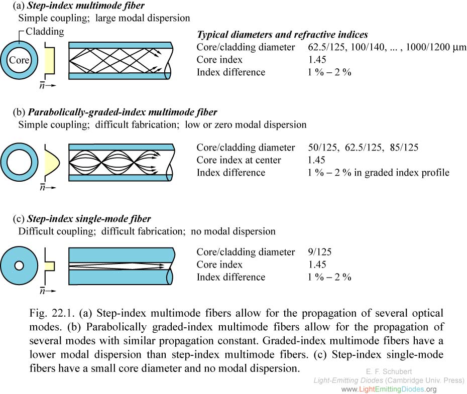
Fig. 22.1. a) Step-index multimode fibers allow for the propagation of several optical modes. (b) Parabolically graded-index multimode fibers allow for the propagation of several modes with similar propagation constant. (c) Step-index single-mode fibers have a small core diameter and no modal dispersion.
|
|
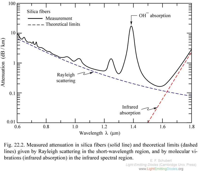
Fig. 22.2. Measured attenuation in silica fibers (solid line) and theoretical limits (dashed lines) given by Rayleigh scattering in the short-wavelength region, and by molecular vibrations (infrared absorption) in the infrared spectral region.
|
|
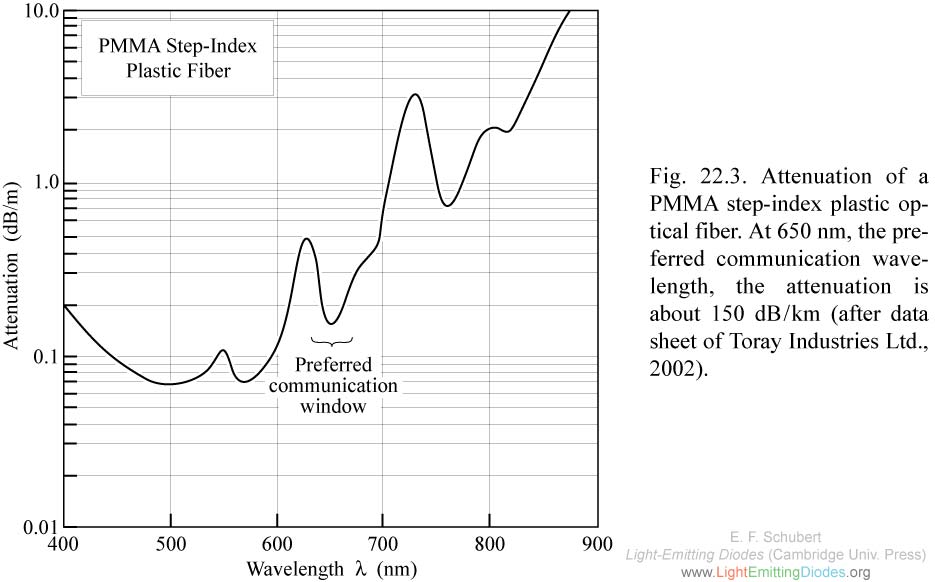
Fig. 22.3. Attenuation of a PMMA step-index plastic optical fiber. At 650 nm, the preferred communication wavelength, the attenuation is about 150 dB/km (after data sheet of Toray Industries Ltd., 2002).
|
|
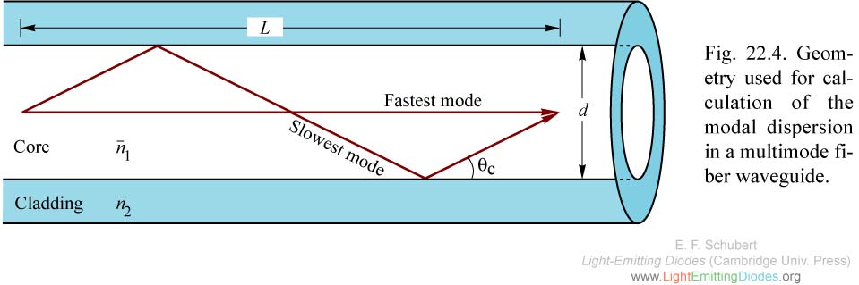
Fig. 22.4. Geometry used for calculation of the modal dispersion in a multimode fiber waveguide.
|
.jpg)
|
Fig. 22.5. Refractive index, group index, and material dispersion of a silica fibers for an optical signal spectral width Delta lambda 0 in vacuum. The material dispersion of regular silica fibers is zero at lambda = 1.3 mu m.
|
|
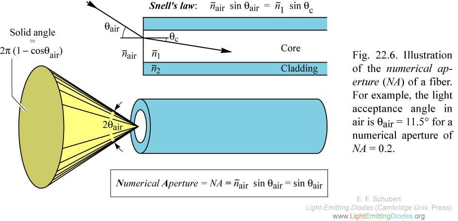
Fig. 22.6. Illustration of the numerical aperture (NA) of a fiber. For example, the light acceptance angle in air is theta air = 11.5° for a numerical aperture of NA = 0.2.
|
|
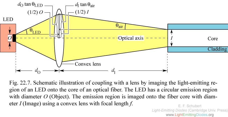
Fig. 22.7. Schematic illustration of coupling with a lens by imaging the light-emitting region of an LED onto the core of an optical fiber. The LED has a circular emission region with diameter O (Object). The emission region is imaged onto the fiber core with diameter I (Image) using a convex lens with focal length f.
|
|
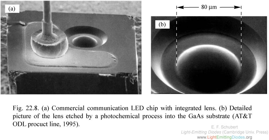
Fig. 22.8. (a) Commercial communication LED chip with integrated lens. (b) Detailed picture of the lens etched by a photochemical process into the GaAs substrate (AT&T ODL procuct line, 1995).
|
|
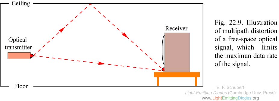
Fig. 22.9. Illustration of multipath distortion of a free-space optical signal, which limits the maximun data rate of the signal.
|