|
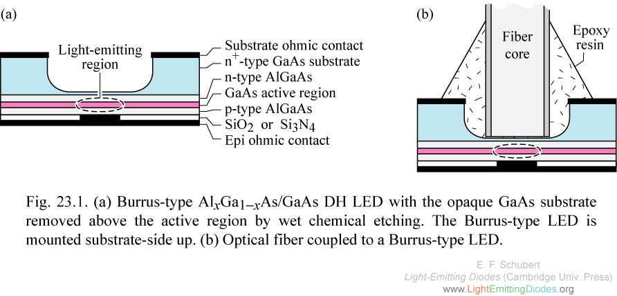
Fig. 23.1. (a) Burrus-type AlxGa1-xAs/GaAs DH LED with the opaque GaAs substrate removed above the active region by wet chemical etching. The Burrus-type LED is mounted substrate-side up. (b) Optical fiber coupled to a Burrus-type LED.
|
|
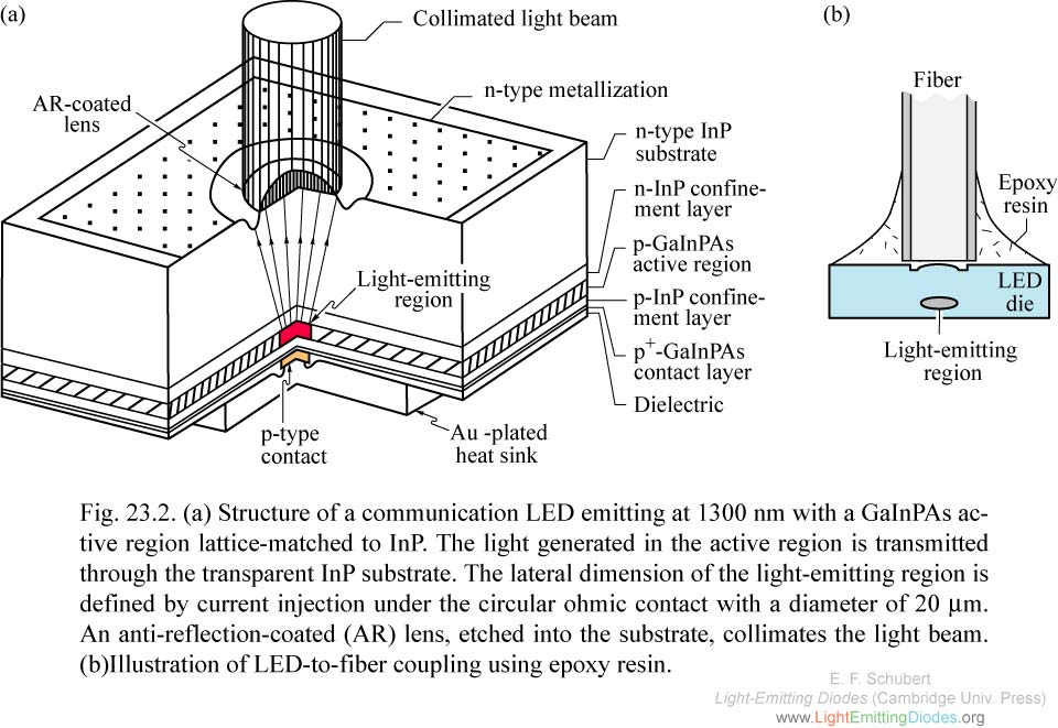
Fig. 23.2. (a) Structure of a communication LED emitting at 1300 nm with a GaInPAs active region lattice-matched to InP. The light generatethe transparent InP substrate. (b)Illustration of LED-to-fiber coupling using epoxy resin.
|
|
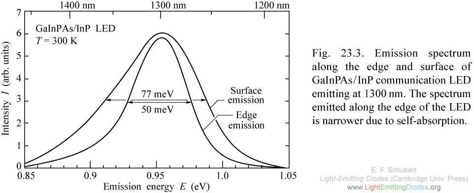
Fig. 23.3. Emission spectrum along the edge and surface of GaInPAs/InP communication LED emitting at 1300nm. The spectrum emitted along the edge of the LED is narrower due to self-absorption.
|
|
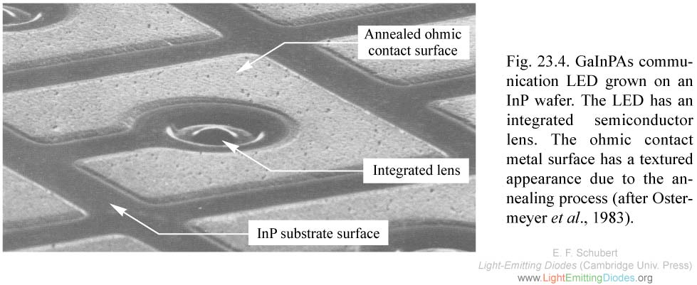
Fig. 23.4. GaInPAs communication LED grown on an InP wafer. The LED has an integrated semiconductor lens. The ohmic contact metal surface has a textured appearance due to the annealing process (after Ostermeyer et al., 1983).
|
|
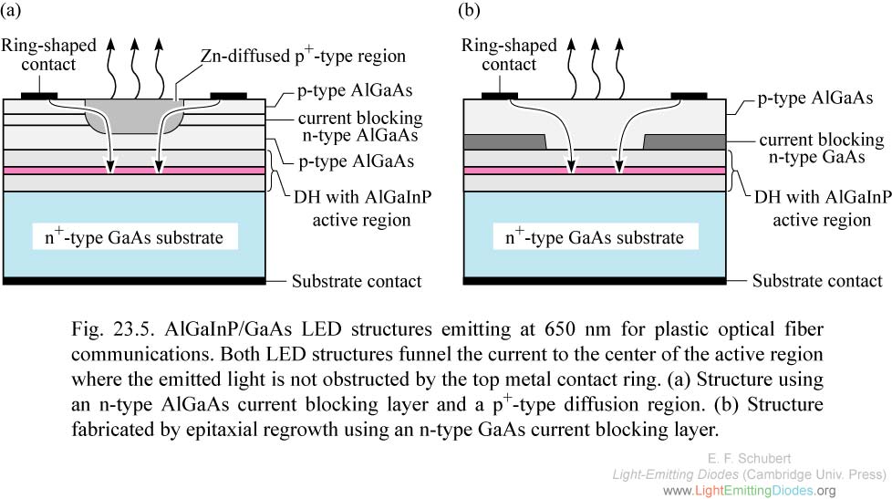
Fig. 23.5. AlGaInP/GaAs LED structures emitting at 650 nm for plastic optical fiber communications. (a) Structure using an n-type AlGaAs current blocking layer and a p+-type diffusion region. (b) Structure fabricated by epitaxial regrowth using an n-type GaAs current blocking layer.
|
|
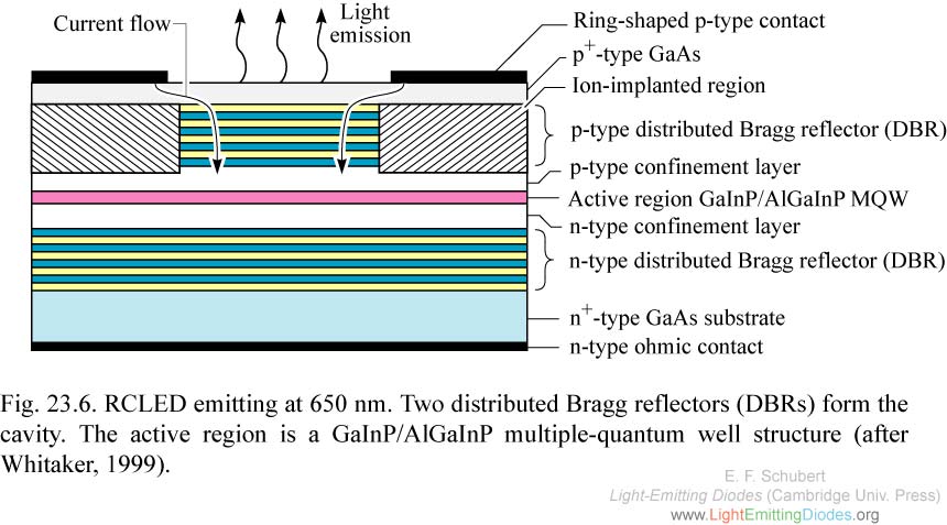
Fig. 23.6. RCLED emitting at 650 nm. Two distributed Bragg reflectors (DBRs) form the cavity. The active region is a GaInP/AlGaInP multiple-quantum well structure (after Whitaker, 1999).
|

|
Fig. 23.7. Fiber-coupled (NA = 0.275) emission spectrum of RCLED and conventional LED at injection current of 30 mA. The microcavity effect of the RCLED enhances the emission intensity and reduces the emission linewidth, especially for low NA fibers (after Whitaker, 1999).
|
|
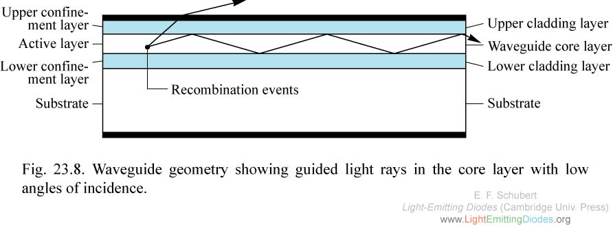
Fig. 23.8. Waveguide geometry showing guided light rays in the core layer with low angles of incidence.
|
|
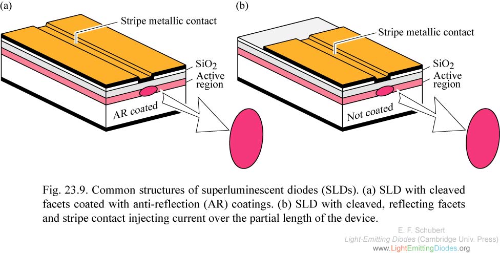
Fig. 23.9. Common structures of superluminescent diodes (SLDs). (a) SLD with cleaved facets coated with anti-reflection (AR) coatings. (b) SLD with cleaved, reflecting facets and stripe contact injecting current over the partial length of the device.
|
|
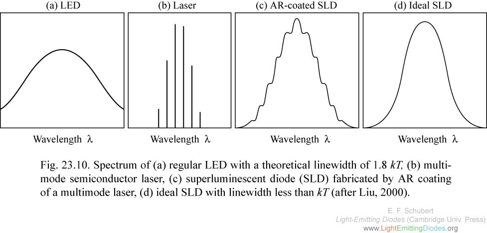
Fig. 23.10. Spectrum of (a) regular LED with a theoretical linewidth of 1.8 kT, (b) multimode semiconductor laser, (c) superluminescent diode (SLD) fabricated by AR coating of a multimode laser, (d) ideal SLD with linewidth less than kT (after Liu, 2000).
|

|
Fig. 23.11. Light-versus-current (L-I) characteristic of different LEDs. (a) Edge-emitting LED with little or no saturation effects. (b) Surface-emitting LED with small active area exhibiting saturation effects due to carrier overflow. (c) Superluminescent LED.
|