|
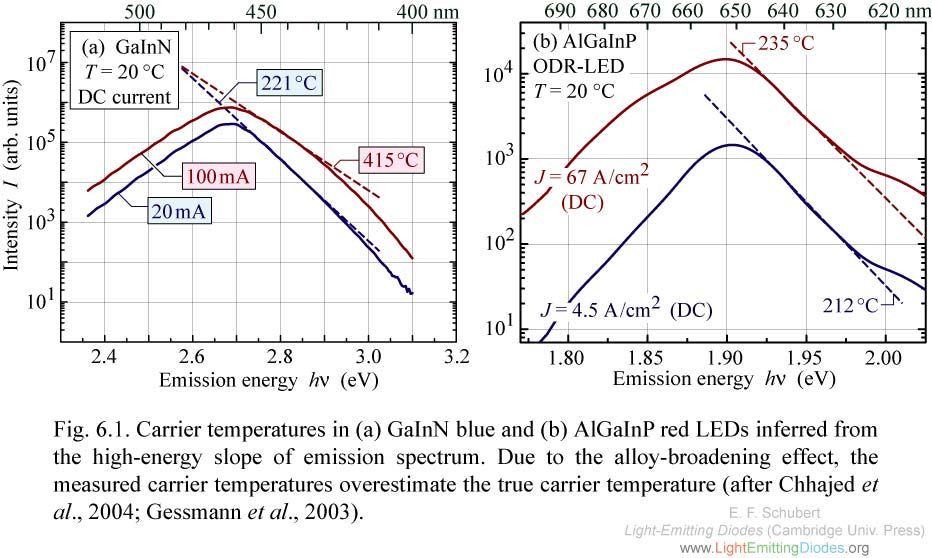
Fig. 6.1. Carrier temperatures in (a) GaInN blue and (b) AlGaInP red LEDs inferred from the high-energy slope of emission spectrum. Due to the alloy-broadening effect, the measured carrier temperatures overestimate the true carrier temperature (after Chhajed et al., 2004; Gessmann et al., 2003).
|
|
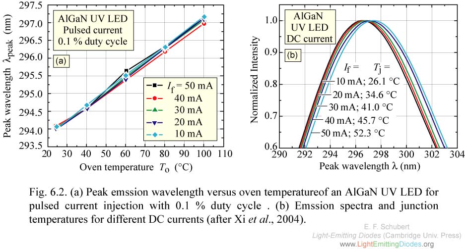
Fig. 6.2. (a) Peak emssion wavelength versus oven temperatureof an AlGaN UV LED for pulsed current injection with 0.1 % duty cycle . (b) Emssion spectra and junction temperatures for different DC currents (after Xi et al., 2004).
|
.jpg)
|
Fig. 6.3. Junction temperature inferred from emission peak energy as a function of DC injection current for a 1 mm × 1 mm deep UV LED emitting at 295 nm. The error bar stems from an uncertainty in the peak energy (after Xi et al., 2004).
|
|
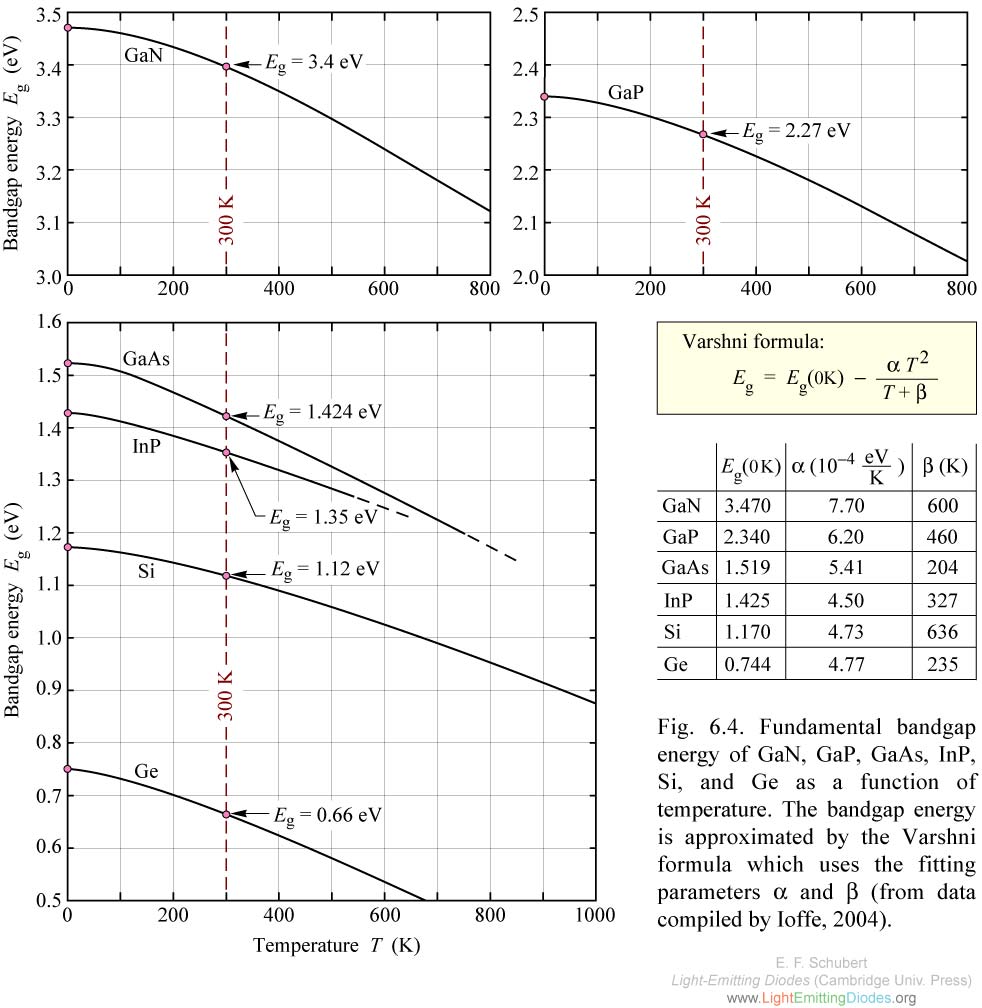
Fig. 6.4. Fundamental bandgap energy of GaN, GaP, GaAs, InP, Si, and Ge as a function of temperature. The bandgap energy is approximated by the Varshni formula which uses the fitting parameters alpha and beta (from data compiled by Ioffe, 2004).
|
|
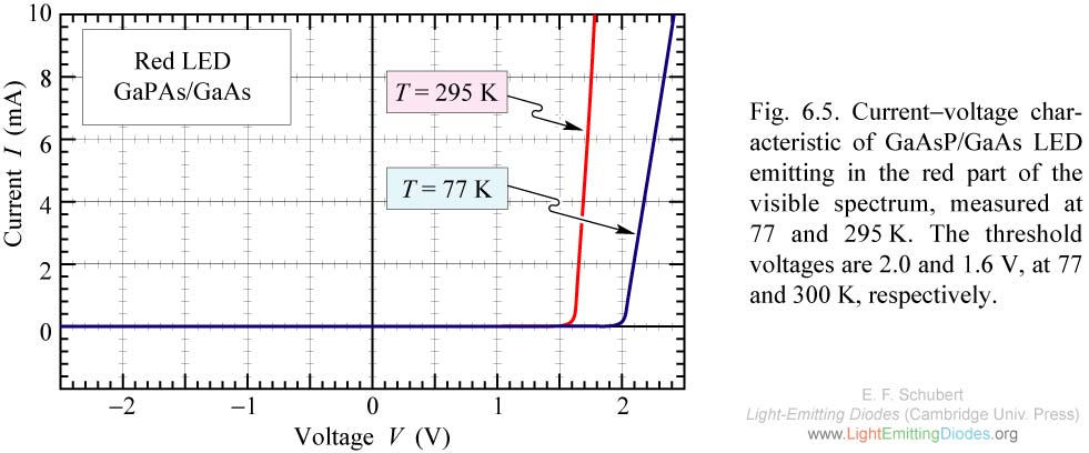
Fig. 6.5. Current-voltage characteristic of GaAsP/GaAs LED emitting in the red part of the visible spectrum, measured at 77 and 295K. The threshold voltages are 2.0 and 1.6 V, at 77 and 300 K, respectively.
|
|
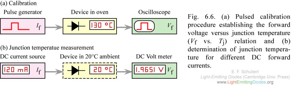
Fig. 6.6. (a) Pulsed calibration procedure establishing the forward voltage versus junction temperature (Vf vs. Tj) relation and (b) determination of junction tempera- ture for different DC forward currents.
|
|
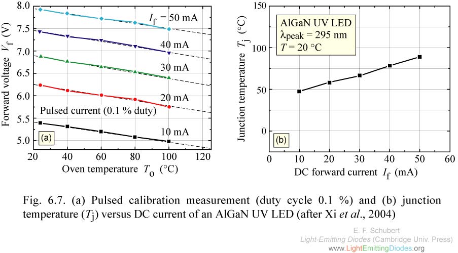
Fig. 6.7. (a) Pulsed calibration measurement (duty cycle 0.1 %) and (b) junction temperature (Tj) versus DC current of an AlGaN UV LED (after Xi et al., 2004).
|
|
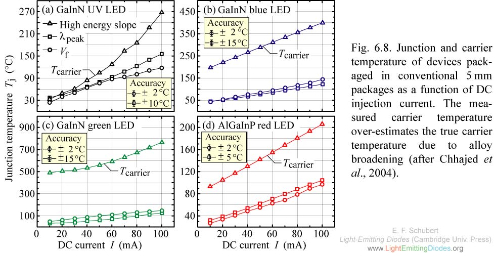
Fig. 6.8. Junction and carrier temperature of devices packaged in conventional 5mm packages as a function of DC injection current. The measured carrier temperature over-estimates the true carrier temperature due to alloy broadening (after Chhajed et al., 2004).
|
|
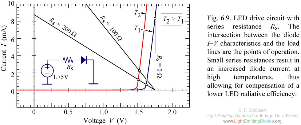
Fig. 6.9. LED drive circuit with series resistance Rs. The intersection between the diode I-V characteristics and the load lines are the points of operation. Small series resistances result in an increased diode current at high temperatures, thus allowing for compensation of a lower LED radiative efficiency.
|