|
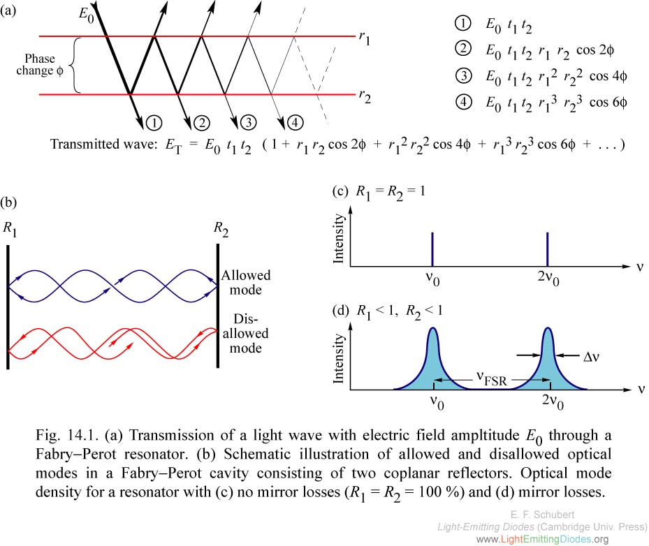
Fig. 14.1. (a) Transmission of a light wave with electric field ampltitude E0 through a Fabry-Perot resonator. (b) Schematic illustration of allowed and disallowed optical modes in a Fabry-Perot cavity consisting of two coplanar reflectors. Optical mode density for a resonator with (c) no mirror losses (R1 = R2 = 100 %) and (d) mirror losses.
|
|
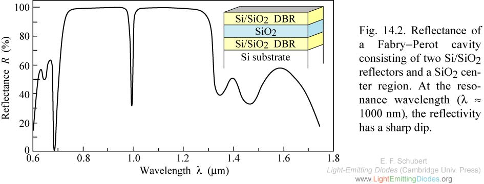
Fig. 14.2. Reflectance of a Fabry-Perot cavity consisting of two Si/SiO2 reflectors and a SiO2 center region. At the resonance wavelength (lambda ≈ 1000 nm), the reflectivity has a sharp dip.
|
|
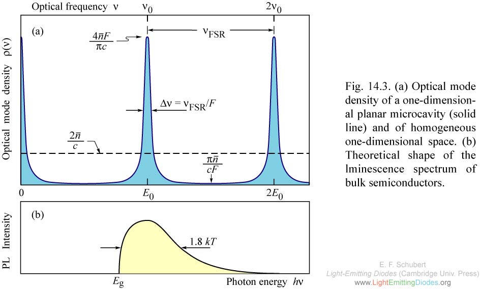
Fig. 14.3. (a) Optical mode density of a one-dimensional planar microcavity (solid line) and of homogeneous one-dimensional space. (b) Theoretical shape of the lminescence spectrum of bulk semiconductors.
|
|
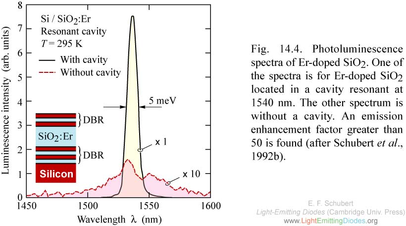
Fig. 14.4. Photoluminescence spectra of Er-doped SiO2. One of the spectra is for Er-doped SiO2 located in a cavity resonant at 1540 nm. The other spectrum is without a cavity. An emission enhancement factor greater than 50 is found (after Schubert et al., 1992b).
|
|
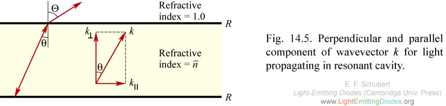
Fig. 14.5. Perpendicular and parallel component of wavevector k for light propagating in resonant cavity.
|
|
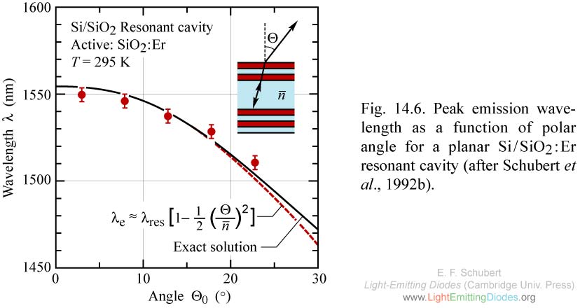
Fig. 14.6. Peak emission wavelength as a function of polar angle for a planar Si/SiO2:Er resonant cavity (after Schubert et al., 1992b).
|
.jpg)
|
Fig. 14.7. Emission spectra of AlGaInP RCLED for different polar angles. The long-wavelength part of the QW emission is emitted in the forward direction (0°). The shorter wavelengths are emitted off-axis. When measured with an integrating sphere, an 18nm wide spectrum (FWHM) is found (after Streubel et al., 2002).
|