
|
Fig. 15.1. Schematic illustration of a resonant cavity consisting of two metal mirrors with reflectivity R1 and R2. The active region has a thickness Lactive and an absorption coefficient alpha. Also shown is the standing optical wave. The cavity length is Lcav is equal to lambda/2.
|
|
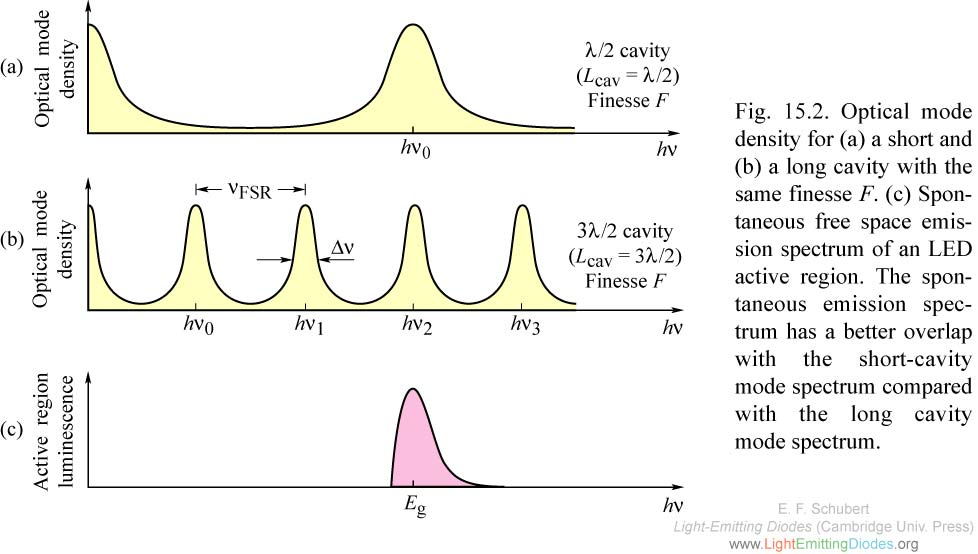
Fig. 15.2. Optical mode density for (a) a short and (b) a long cavity with the same finesse F. (c) Spontaneous free space emission spectrum of an LED active region. The spontaneous emission spectrum has a better overlap with the short-cavity mode spectrum compared with the long cavity mode spectrum.
|
|
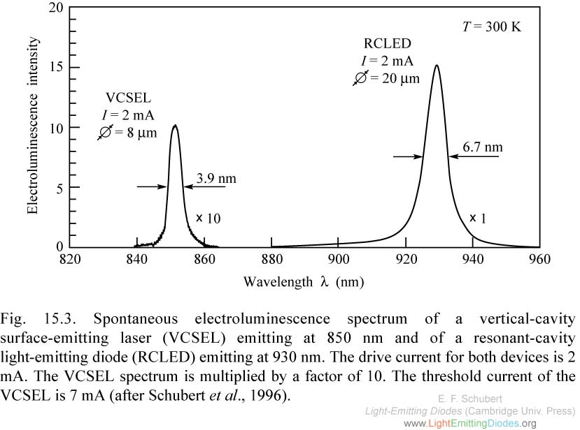
Fig. 15.3. Spontaneous electroluminescence spectrum of a vertical-cavity surface-emitting laser (VCSEL) emitting at 850 nm and of a resonant-cavity light-emitting diode (RCLED) emitting at 930 nm. (after Schubert et al., 1996).
|
|
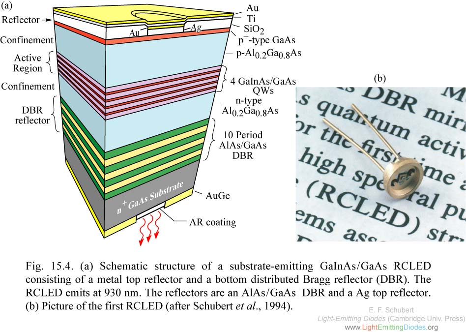
Fig. 15.4. (a) Schematic structure of a substrate-emitting GaInAs/GaAs RCLED consisting of a metal top reflector and a bottom distributed Bragg reflector (DBR). The RCLED emits at 930 nm. The reflectors are an AlAs/GaAs DBR and a Ag top reflector. (b) Picture of the first RCLED (after Schubert et al., 1994).
|

|
Fig. 15.5. (a) Reflectance of a resonant cavity consisting of a 10-pair AlAs/GaAs distributed Bragg reflector and an Ag reflector. (b) Emission spectrum of a RCLED consisting of a 10-pair AlAs/ GaAs distributed Bragg reflector and an Ag reflector (after Schubert et al., 1994).
|
|
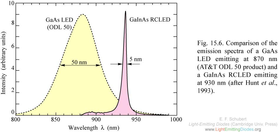
Fig. 15.6. Comparison of the emission spectra of a GaAs LED emitting at 870 nm (AT&T ODL 50 product) and a GaInAs RCLED emitting at 930 nm (after Hunt et al., 1993).
|
|
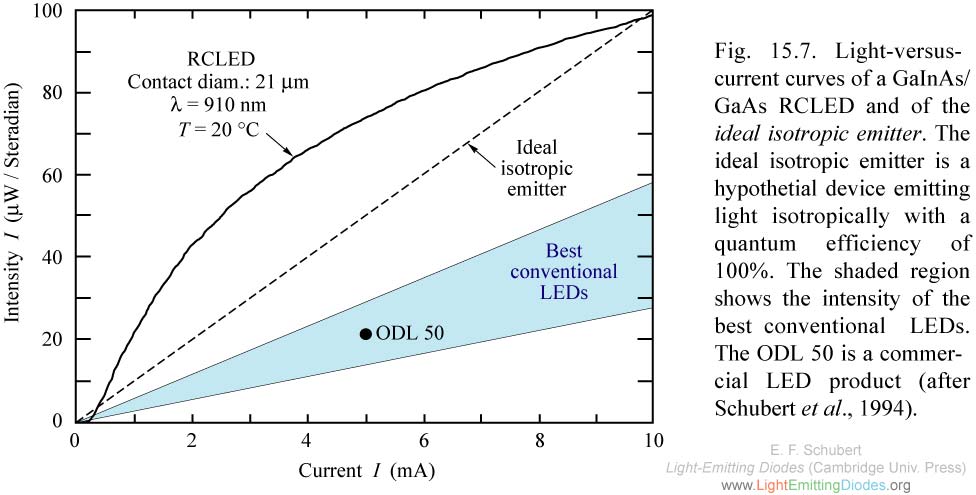
Fig. 15.7. Light-versus-current curves of a GaInAs/ GaAs RCLED and of the ideal isotropic emitter. The ideal isotropic emitter is a hypothetial device emitting light isotropically with a quantum efficiency of 100% (after Schubert et al., 1994)
|
|
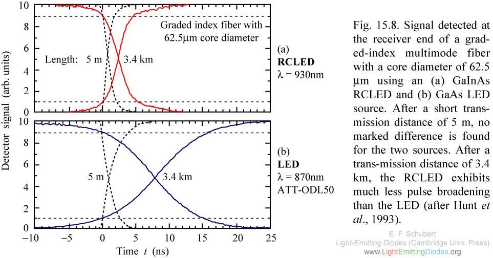
Fig. 15.8. Signal detected at the receiver end of a graded-index multimode fiber with a core diameter of 62.5 mm using an (a) GaInAs RCLED and (b) GaAs LED source. (after Hunt et al., 1993).
|
|
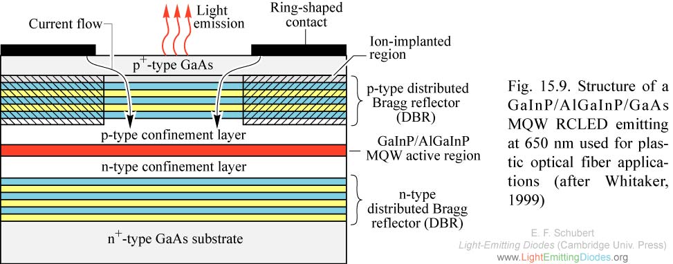
Fig. 15.9. Structure of a GaInP/AlGaInP/GaAs MQW RCLED emitting at 650 nm used for plastic optical fiber applications (after Whitaker, 1999)
|
|
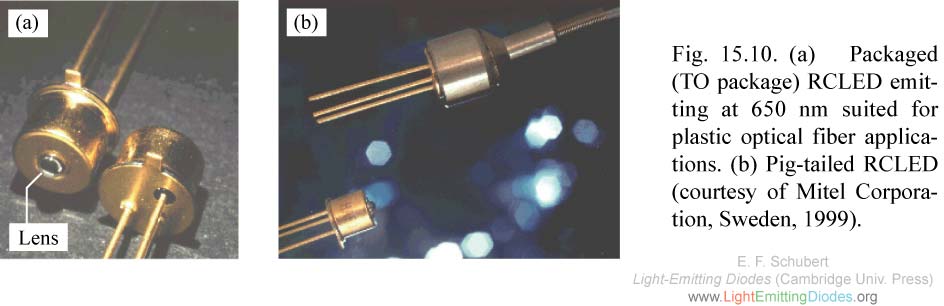
Fig. 15.10. (a) Packaged (TO package) RCLED emitting at 650 nm suited for plastic optical fiber applications. (b) Pig-tailed RCLED (courtesy of Mitel Corporation, Sweden, 1999).
|
|
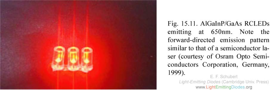
Fig. 15.11. AlGaInP/GaAs RCLEDs emitting at 650nm. Note the forward-directed emission pattern similar to that of a semiconductor laser (courtesy of Osram Opto Semiconductors Corporation, Germany, 1999).
|
|
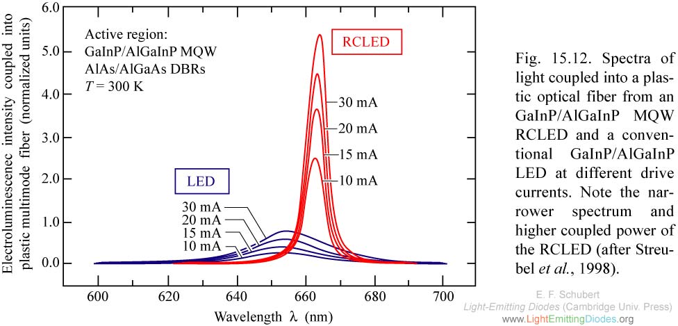
Fig. 15.12. Spectra of light coupled into a plastic optical fiber from an GaInP/AlGaInP MQW RCLED and a conventional GaInP/AlGaInP LED at different drive currents. Note the narrower spectrum and higher coupled power of the RCLED (after Streubel et al., 1998).
|
|
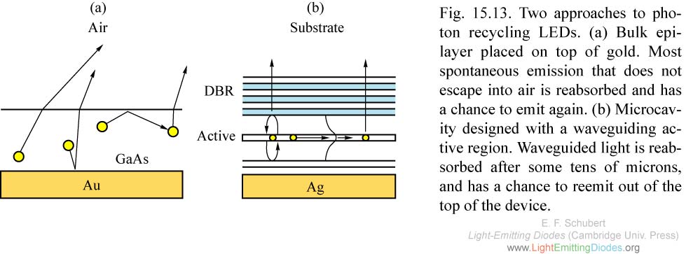
Fig. 15.13. Two approaches to photon recycling LEDs. (a) Bulk epilayer placed on top of gold. Most spontaneous emission that does not escape into air is reabsorbed and has a chance to emit again. (b) Microcavity designed with a waveguiding active region.
|
|
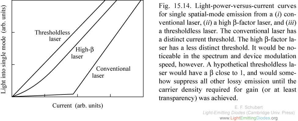
Fig. 15.14. Light-power-versus-current curves for single spatial-mode emission from a (i) conventional laser, (ii) a high beta-factor laser, and (iii) a thresholdless laser.
|